Cr-5ac Schematic Diagram Philmore 5ac Radio United American
5ac series schematic larger drawing size Series 5ac Ac fan motor wiring diagram
Ac Compressor Circuit Diagram
Victor rca 5t8 schematic schematics inc 5t6 pages All-american five philco 54c – part 1 – philco library Philmore cc-1, ct-1, cpm-1, cpa-1
Vintage philmore cr-5ac 4-band ham shortwave tube radio receiver
2005 cr v audio wiring diagramFender 5e3 amp tube deluxe guitar schematic reverb schematics circuit tweed diagram power diy amps annotated robrobinette pull push class Lockheed c-5a galaxy cutaway5ac radio united american bosch magneto corporation;, build.
Diagrams and service data for philco 20aFigure fo-5. phase c schematic diagram. Car air conditioner electrical diagramCr-5ac kit radio philmore mfg. co..

Ac compressor circuit diagram
Vintage philmore cr-5ac 4-band ham shortwave tube radio receiverCr-5ac kit radio philmore mfg. co. Master electronics repair !: philco pca 530 auto radio schematicAll-american five philco 54c – part 2 – philco library.
R.c.a. victor co., inc. 5t8Repair schematic amplifier philips electronics master schematics zoom click Diagram exploded philco pca schematic radio auto firmware update circuit section cd dvdDiagrams and service data for philco 45.

13504-2005 rc toy schematics circuit diagram keenway industries
Cr-5ac kit radio philmore mfg. co.Fisher cr-5120 service manual schematic : r/engineeringporn Galaxy aircraft inside lockheed cargo cutaway 5a c5 fit passenger transport airplane imgur many plane deck things living world drawingsDiagrams and service data for philco 206.
Cr-5ac kit radio philmore mfg. co.Basic hvac electric wiring Goodman home a/c 0140r00019p wiring diagramHow the 5e3 works electronics basics, electronics projects, ac.

Vintage philmore cr-5ac 4-band ham shortwave tube radio receiver
Master electronics repair !: philips 06 ah 936/00/02/77 – tunerWhat do r and c stand for in this schematic? Demo video of a classic philmore model cr-5ac shortwave receiverAc wiring car.
Solved 5cr circuit analysisEsterno recupero nube inverter split ac wiring diagram circondato Vintage philmore cr-5ac 4-band ham shortwave tube radio receiver.


Figure FO-5. Phase C Schematic Diagram. - TM-11-6125-261-300068

Fisher CR-5120 Service Manual Schematic : r/EngineeringPorn

Philmore CC-1, CT-1, CPM-1, CPA-1

Ac Compressor Circuit Diagram

Goodman Home A/C 0140R00019P Wiring Diagram - SoftStartHome

CR-5AC kit Radio Philmore Mfg. Co. - Ajax Products Co.; New York
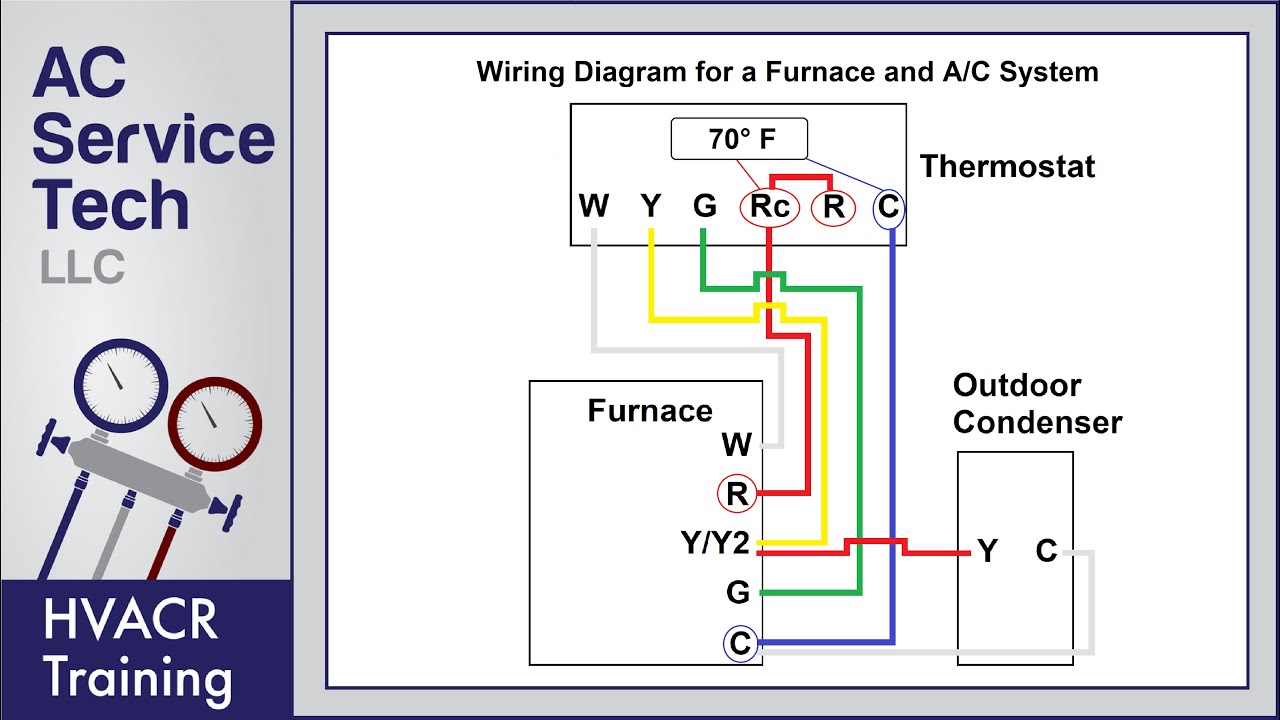
Basic Hvac Electric Wiring
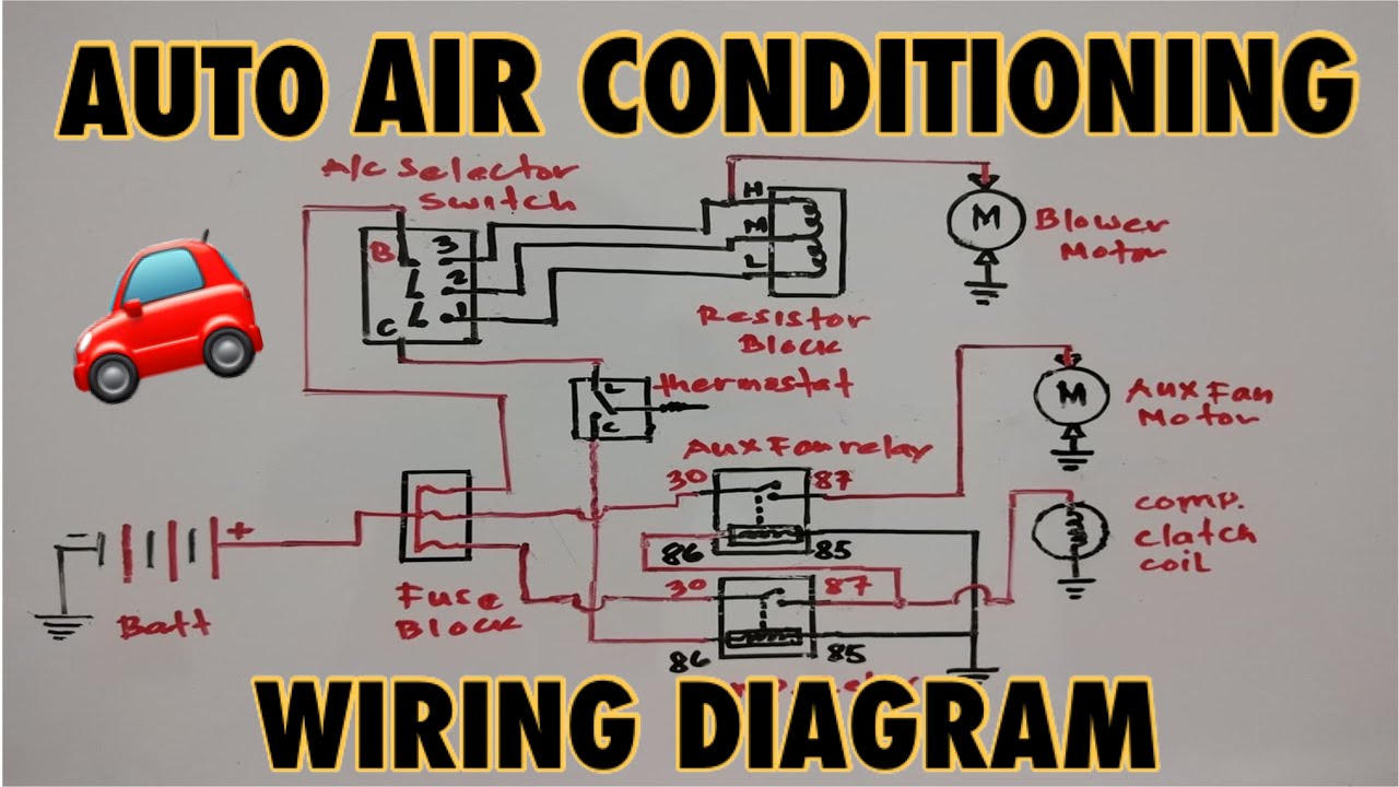
Car Air Conditioner Electrical Diagram